By using this site you agree to the use of cookies by the company in accordance with the Privacy Policy
Why Choose a Hydraulic Pedal Lever Valve?
A Hydraulic Pedal Lever Valve converts foot pressure into controlled hydraulic movement. It gives operators direct command while leaving both hands available for machine tasks. In a compact excavator, one foot press can redirect oil through a spool and begin smooth actuator movement. That physical connection matters when visibility, balance, and response time are limited.
Market evidence supports continued investment in hydraulic control systems. Grand View Research estimated the global hydraulic equipment market at approximately USD 49 billion in 2023. Its report also projects steady growth through 2030, driven by construction, agriculture, material handling, and industrial automation. MarketsandMarkets has similarly identified valves and motion-control components as important parts of expanding fluid-power systems. These estimates differ by methodology. They should not be treated as universal predictions.
A pedal lever valve offers practical advantages over hand-only control in selected applications. It can reduce hand fatigue, simplify operator coordination, and provide predictable directional control. Proper sizing remains essential. Flow rate, pressure rating, spool configuration, return mechanism, and mounting position must match the circuit. ISO 4413 emphasizes safe hydraulic system design, including pressure control and stored-energy management. The component alone cannot guarantee safety. That assumption needs testing.
In field service, small details matter. A dusty pedal, stiff spring, or leaking fitting can change the operator’s response. Regular inspection should include seal condition, pedal travel, hose connections, and neutral return. It is not a magic lever. Yet, when engineered correctly, a Hydraulic Pedal Lever Valve can deliver durable, intuitive, and efficient control for demanding equipment.
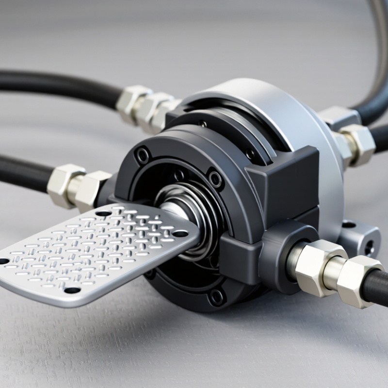
Why Choose a Hydraulic Pedal Lever Valve?
What Is a Hydraulic Pedal Lever Valve?
A hydraulic pedal lever valve is a manually controlled valve operated by a foot pedal or hand lever. It directs hydraulic fluid toward an actuator, often a cylinder or motor. When the operator presses the pedal, an internal spool shifts and opens a flow path. Releasing the pedal returns the spool, allowing the circuit to stop, reverse, or hold pressure. The exact action depends on the valve’s ports and center configuration.
In practical equipment, this control feels immediate. A foot movement can raise a platform, clamp a workpiece, or steer a compact machine. The operator keeps both hands available. That matters during repetitive tasks. However, response is influenced by oil viscosity, contamination, pedal travel, and system pressure. A stiff pedal may indicate linkage wear, not a defective hydraulic section. I have found that simple inspections often prevent inaccurate adjustments.
Choosing one requires more than matching thread size. Check rated pressure, flow capacity, port arrangement, return method, and mounting space. Confirm that the pedal’s neutral position matches the machine’s safe operating condition. Clean fluid and a suitable filter protect the spool from sticking. Small details matter. It is easy to assume the valve is the problem, but circuit data may suggest otherwise. One imperfect assumption can cause slow movement or unexpected drift.
A hydraulic pedal lever valve controls fluid movement through foot pressure. When an operator presses the pedal, the lever shifts an internal spool. This spool opens specific passages between the pressure, return, and actuator ports. Pressing one side may send oil to extend a cylinder. Pressing the other side reverses the flow. Releasing the pedal allows a spring or centering mechanism to return the spool. The actuator then slows or stops, depending on the circuit design.
The response depends on pedal travel, hydraulic pressure, spool clearance, and load resistance. A small movement can produce gentle motion, while deeper pressure allows greater flow. In practical maintenance work, operators often notice control changes before visible leaks appear. The pedal may feel stiff, delayed, or uneven. These signs should not be ignored. Still, pedal feel alone cannot confirm the fault. Contamination, trapped air, worn seals, or incorrect adjustment can create similar symptoms.
Tips: Keep the fluid clean and inspect fittings regularly. Check that the pedal returns freely after release. Test movement with no unnecessary load first. Never assume a slow actuator needs more pressure. Excess pressure may hide a control problem and increase component stress. A service manual and pressure gauge provide more reliable evidence than guesswork.
Why Choose a Hydraulic Pedal Lever Valve?
A hydraulic pedal lever valve lets operators control fluid movement with their feet. This foot-controlled design keeps both hands available for guiding tools, adjusting loads, or holding work securely. That matters in compact work areas, where hand controls can feel crowded. A light pedal press can provide gradual valve movement, helping operators manage speed with better control. The response still depends on system pressure, valve sizing, and pedal adjustment.
In practical hydraulic work, foot control can reduce repeated hand movements during long operating cycles. It may also improve coordination when the operator must watch a cylinder, clamp, or lifting attachment closely. The pedal position gives a clear physical reference. Operators can feel movement through their shoes, although this feedback is not always precise. It is not perfect. Poor footwear, fatigue, or accidental contact can affect control. A guarded pedal and a reliable return spring are important design details.
Tips: Check the pedal’s full travel before operation. Confirm that the valve returns to neutral without sticking. Keep the control area dry and free from loose materials. Test movement at low pressure first. Record unusual resistance or delayed response during inspections. A small delay may indicate contamination, worn seals, or incorrect adjustment. Do not ignore it. Good maintenance records also help technicians identify changing valve behavior before performance becomes unpredictable.
| Design Dimension | Hydraulic Pedal Lever Valve | Practical Advantage | Important Selection Consideration |
|---|---|---|---|
| Actuation method | Mechanical foot pedal connected to a hydraulic directional control spool | Allows the operator to control hydraulic movement with the foot while keeping both hands available. | Confirm that the pedal position is reachable and does not interfere with other foot-operated controls. |
| Operator hand availability | Control is transferred from the hand to the foot | The operator can simultaneously hold a workpiece, guide an attachment, or use another hand-operated function. | The design is most useful when hand coordination is required during hydraulic actuation. |
| Directional control | Spool position directs pressurized fluid to selected actuator ports | Supports functions such as cylinder extension, cylinder retraction, or motor direction control, depending on the valve configuration. | The number of positions and working ports must match the hydraulic circuit schematic. |
| Control response | Direct mechanical linkage provides immediate spool movement when the pedal is pressed | Offers predictable command transmission without requiring an electrical signal or software control. | Actual actuator response also depends on flow rate, load, hose length, restriction, and hydraulic-fluid condition. |
| Control modulation | Pedal travel may provide on/off or proportional control, depending on spool design and linkage geometry | A proportional arrangement can help the operator adjust actuator speed more smoothly than a simple two-position control. | Do not assume proportional operation; verify the valve’s spool type, travel, and rated flow characteristics. |
| Return behavior | May use spring return, detent, or another mechanical return arrangement | A spring-return configuration can return the control toward its neutral position when foot pressure is removed. | Return behavior is configuration-dependent and must be checked against the machine’s safety requirements. |
| Ergonomics | Large pedal surface can be operated through normal footwear | Can reduce repeated hand movement during cycles that require frequent directional changes. | Pedal height, angle, travel, operating force, and clearance should be evaluated before installation. |
| Installation flexibility | Can be mounted in a foot-control area and connected directly to hydraulic lines | Provides a simple control layout where an electrical foot switch or remote electronic interface is unnecessary. | Check mounting dimensions, port orientation, access for maintenance, and protection from impact or debris. |
| Hydraulic compatibility | Performance depends on the valve’s rated pressure, rated flow, port size, and fluid compatibility | Correct matching helps prevent excessive pressure drop, overheating, leakage, and premature component wear. | Use the valve’s technical data sheet; pressure and flow ratings are not universal across pedal valve designs. |
| Best-fit applications | Equipment requiring hands-free directional control or repeated hydraulic cycling | Suitable for selected machinery, workholding systems, compact hydraulic equipment, and operator stations with foot-accessible controls. | Avoid the arrangement where the operator must keep both feet occupied for balance, travel, braking, or another safety-critical function. |
Selecting the right hydraulic pedal lever valve starts with the machine’s real operating conditions. Hydraulic equipment is expanding steadily. Grand View Research valued the global market at about USD 49.06 billion in 2023, with continued growth expected through 2030. That growth increases the need for reliable, correctly sized control valves.
Check working pressure, flow rate, port size, and fluid compatibility before comparing prices. The valve’s rated pressure should exceed the system’s maximum pressure, not merely its normal pressure.
Flow capacity also matters. An undersized valve can create heat, slow actuator movement, and waste energy. Review ISO 4413 guidance for hydraulic safety and contamination control. A dusty workshop may require stronger sealing and easier maintenance access.
Pedal feel deserves practical testing.
Choose spring return when the actuator must stop after release. Choose detent action only when the operator needs a stable position. Measure the required foot force with safety footwear, not bare feet.
Small details matter. MarketsandMarkets has projected continued growth in hydraulic equipment demand, making lifecycle performance more important than the initial purchase price.
Ask for pressure-drop curves, cycle-test results, and temperature limits. A valve may look suitable on paper, yet feel awkward during a twelve-hour shift. I would also test several samples, because catalogue tolerances rarely show every field condition.
Hydraulic pedal lever valves are commonly used where operators need hands-free hydraulic control. They convert foot movement into a controlled hydraulic signal or flow path. In compact excavators, operators may use them for auxiliary attachments or precise boom movements. The pedal leaves both hands available for steering, positioning, and monitoring the work area. It also provides direct feedback through foot pressure. That physical response can help during slow, careful movements. However, it is not always the best choice. Long operating cycles may cause fatigue, especially when the pedal requires constant pressure.
These valves also appear in compact loaders, lifting platforms, agricultural machinery, and material-handling equipment. They suit tasks requiring repeated directional changes, such as opening a clamp, adjusting a platform, or controlling an attachment. Industrial presses and production fixtures may use pedal operation when the machine layout supports safe foot access. Guards, emergency stops, and controlled return functions remain important. A convenient pedal should never encourage unsafe positioning.
Technicians usually check the working pressure, flow capacity, spool configuration, and return mechanism before installation. The neutral position must match the machine’s hydraulic circuit. Contaminated oil can make the pedal feel stiff or inconsistent. That detail is easy to miss. A valve may perform well during a clean test, then respond poorly in dusty field conditions. Regular inspection should include leakage, loose linkages, damaged springs, and unusual pedal resistance. Small installation errors can affect control accuracy.
By using this site you agree to the use of cookies by the company in accordance with the Privacy Policy
Have a questions or want to know more about our company? We'll be expecting you.